

Comparing Neodymium Magnets for Electric Motor Designs
Choosing neodymium magnets for electric motors is not a matter of selecting the largest grade number on a catalog page. A motor designer has to balance useful air-gap flux, demagnetization margin, thermal exposure, geometry, manufacturing tolerance, and corrosion protection. As a magnetic-materials technical specialist, I would start with the working conditions and magnetic circuit, then compare grades that can survive them.
The question most teams begin with is “which magnet is strongest?” A better question is “what temperature, opposing field, air gap, and assembly tolerance will this rotor actually see?” That shift narrows the right options for neodymium magnets for electric motors long before a pull-force figure is considered.
Start with the motor’s real operating envelope
For neodymium magnets for electric motors, the relevant temperature is not simply the ambient temperature outside the housing. Consider rotor heating, nearby windings, duty cycle, ventilation, thermal cycling, and fault conditions. A standard N-grade NdFeB magnet is often associated with a maximum operating temperature near 80°C, while higher-coercivity classes can extend the usable range; SH classes are commonly cited around 150°C. Those figures are starting points, not release criteria. Confirm the exact grade, load line, and temperature limit with the supplier’s current data sheet.
If an application stays below 60°C continuously, a standard grade may be appropriate. If repeated thermal cycling brings the magnet close to its rating, the picture changes. In that situation, neodymium magnets for electric motors should be evaluated for irreversible loss after the full temperature-and-field combination, not only at room temperature.
Compare remanence and coercivity instead of grade labels alone
Motor teams often compare energy-product labels first. That can be useful, but it is incomplete. Remanence is associated with the flux a magnet retains after magnetization, while coercivity describes resistance to demagnetization. In a compact rotor, higher remanence can help achieve flux density, yet insufficient coercivity can leave a design vulnerable when heat and an opposing stator field act together.
For this reason, comparing neodymium magnets for electric motors should include at least the residual flux density, intrinsic coercivity, maximum operating temperature, and the proposed operating point on the demagnetization curve. There is no universally better choice: the appropriate grade depends on your operating condition and tolerance requirement. If thermal margin is the priority, coercivity deserves more attention than a headline pull-force number.
Use the magnetic circuit, not a bench pull test, as the comparison basis
A catalog pull-force test is usually performed against a defined steel target with a specified contact condition. A motor has an air gap, rotor back iron, slotting effects, curved or segmented magnets, and changing current. None of those conditions is reproduced by a simple pull test. When comparing neodymium magnets for electric motors, model or measure the assembled magnetic circuit and inspect air-gap flux, back-emf, torque constant, cogging behavior, and demagnetization margin.
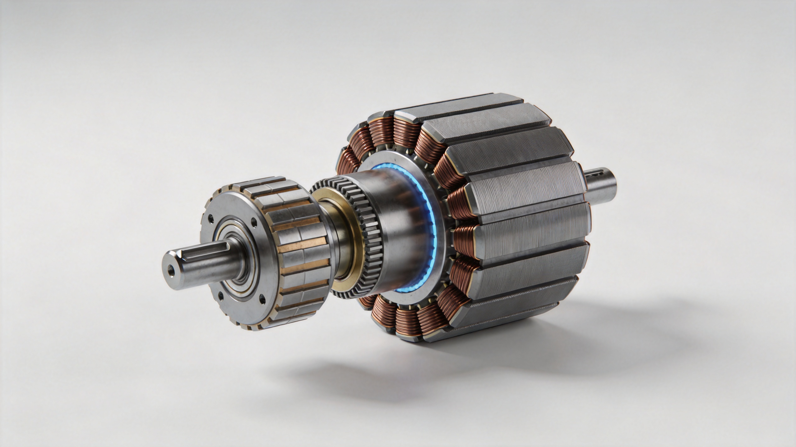
Geometry matters as much as material. Radial segments, arc magnets, blocks, and rings place flux differently in the rotor. A thin magnet may need a different grade or pole arrangement than a thicker magnet with the same nominal volume. Magnetization direction, pole count, and retention method also influence what a practical specification can deliver. Treat the magnet, adhesive or sleeve, back iron, and air gap as one system.
Bring tolerance decisions forward in the design
The moment to define tolerance for neodymium magnets for electric motors is not after the rotor housing is frozen. By then, the remaining choices can be limited to sorting, rework, or redesign. Thickness variation changes the air gap; arc-angle and radius variation can affect pole coverage; and cumulative stack-up can alter rotor balance or adhesive clearance.
On paper, a broad tolerance can look acceptable. At assembly, variation across a production lot may create inconsistent retention force or an uneven air gap. Specify the critical dimensions, measurement datum, chamfers, coating thickness allowance, and inspection method early. For sintered magnets, also discuss whether tight tolerances require grinding and how that changes lead time, yield, and cost. This does not mean every dimension needs the tightest limit; it means the limits must match the motor sensitivity.
Compare coatings and handling requirements
Most sintered neodymium magnets for electric motors need protection because NdFeB is susceptible to corrosion. The suitable coating depends on humidity, salt exposure, oil, adhesive, assembly temperature, and any risk of edge damage. Nickel-based systems, epoxy systems, and other options can perform differently in a given process. Do not assume that a coating used in a dry indoor assembly will be enough for a humid or chemically exposed motor environment.
Handling is also part of selection. Strong magnets can chip when they snap together, and coating damage can start a later corrosion issue. Define separation methods, magnetization state during assembly, orientation checks, and packaging. These process details are easy to overlook when comparing neodymium magnets for electric motors, but they affect repeatability.
A practical comparison checklist
- Define continuous, peak, and fault temperatures at the magnet location.
- Compare remanence, intrinsic coercivity, and temperature class for the actual load line.
- Evaluate air-gap flux and demagnetization in the assembled motor circuit.
- Choose geometry, magnetization direction, and pole coverage with the rotor topology.
- Set critical dimensional and coating tolerances before tooling is finalized.
- Qualify corrosion protection, adhesive compatibility, handling, and incoming inspection.
Make the final choice with a prototype plan
The strongest-looking specification is not automatically the safest production choice. A disciplined comparison of neodymium magnets for electric motors ends with prototypes that represent the intended geometry, coating, adhesive, and thermal condition. Test back-emf, torque, rotor balance, temperature rise, and any irreversible change after relevant thermal cycling. Keep supplier certificates and lot-level inspection records aligned with the dimensions and magnetic values that matter to the motor.
In short, selecting neodymium magnets for electric motors is a system-design decision. Begin with temperature and demagnetizing conditions, verify grade data against the operating point, and then close the gap between a catalog specification and the assembled rotor. That process produces a comparison that is more useful than simply ordering the highest available grade.


